


For detailed information, other images and documents, please select individual articles from the following table.


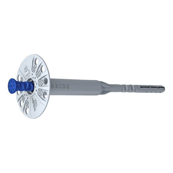
Insulation panel anchor R-TFIX-8M
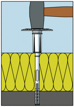
With galvanised steel nail

Register now and access more than 125,000 products

Variants
Register now and access more than 125,000 products
Customer Service: 0471 828 000 or text us on Whatsapp
Prices for customers after login
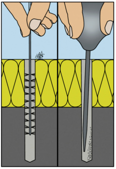
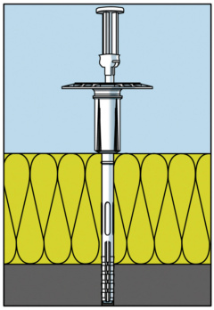
- Polypropylene anchor preassembled with galvanised steel nail surmounted by fibreglass-reinforced polyamide pin
- Thanks to its particular geometry, the anchor can transfer high loads to the support with a shallower anchoring depth
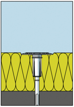
- Reduced heat transfer compared to traditional hammer drive pins with galvanised steel nail χ = 0.001 W/K
For soft insulation panels (e.g. made of rock wool), the KWL retaining plate (dia. 90 mm) can be used
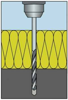
A tolerance of 10 mm (e.g. adhesive) is already accounted for. The presence of layers of plaster on older buildings, for example, reduces the maximum thickness of the insulation panel. For this reason, the specific installation situation should always be considered when calculating the length of the anchor
The load capacity values indicated refer to static anchor loads without influence from edges or other anchors
Rk, Rd, Ramm are respectively characteristic, design and permissible resistance values. The characteristic and design values are obtained using statistical methods
and safety factors. The permissible value is obtained from the design value by applying an additional conventional safety factor of 1.4. For those unfamiliar with the characteristic and design values, we recommend using the permissible strength value by checking that it is greater than the maximum load acting on the anchor
| Supports A + B + C + D | Support E | ||||||
| Min. depth of hole [mm] | Min. depth of anchor [mm] | Max. thickness of insulation panel1) [mm] | Min. depth of hole [mm] | Min. depth of anchor [mm] | Max. thickness of insulation panel1) mm | Length of anchor [mm] | Art. |
| 35 | 25 | 100 | 75 | 65 | 60 | 135 | 5921 397 135 |
| 120 | 80 | 155 | 5921 397 155 | ||||
| 140 | 100 | 175 | 5921 397 175 | ||||
| 160 | 120 | 195 | 5921 397 195 | ||||
| 180 | 140 | 215 | 5921 397 215 | ||||
| 200 | 160 | 235 | 5921 397 235 | ||||
| 220 | 180 | 255 | 5921 397 255 | ||||
| 240 | 200 | 275 | 5921 397 275 | ||||
| 260 | 220 | 295 | 5921 397 295 | ||||
| 1) A tolerance of 10 mm (e.g. adhesive) is already accounted for. The presence of layers of plaster on older buildings, for example, reduces the maximum thickness of the insulation panel. For this reason, the specific installation situation should always be considered when calculating the length of the anchor. | |||||||
| Base material | Category | Rk characteristic resistance to extraction | Rd design resistance to extraction | Ramm permissible (or recommended) load |
| Permissible maximum loads and installation conditions: | ||||
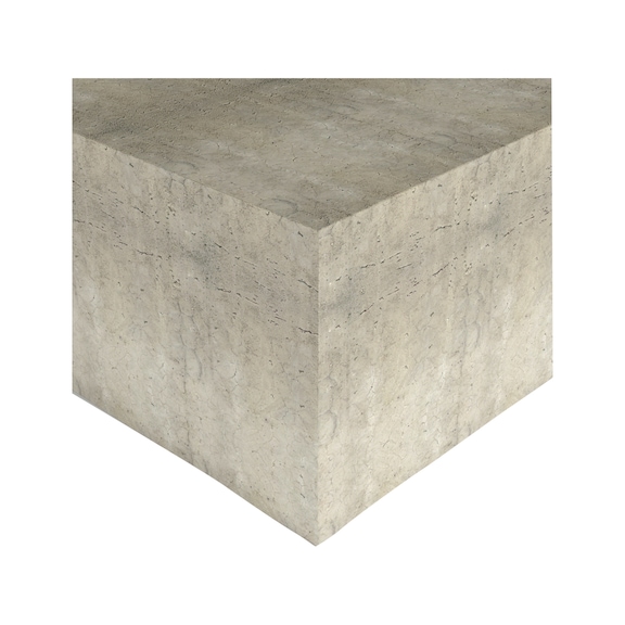
| Concrete C12/15 | A | 1.10 kN | 0.55 kN | 0.39 kN |
| Concrete C16/20 - C50/60 | A | 1.20 kN | 0.60 kN | 0.43 kN |
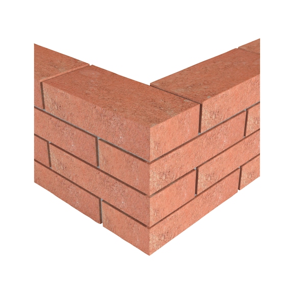
| Solid bricks | B | 1.20 kN | 0.60 kN | 0.43 kN |
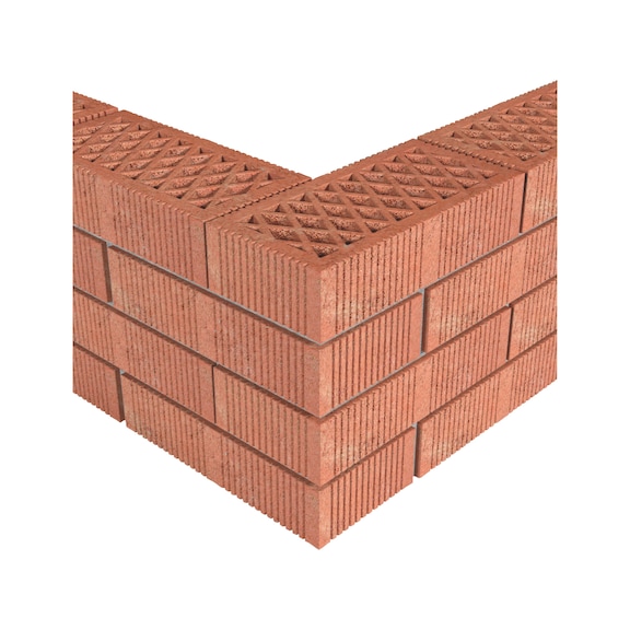
| Perforated bricks | C | 1.10 kN | 0.55 kN | 0.39 kN |
| Lightweight concrete | D | 0.50 kN | 0.25 kN | 0.18 kN |
| Autoclaved aerated (cellular) concrete | E | 1.00 kN | 0.50 kN | 0.36 kN |
| Min. spacing between anchors | A, B, C, D, E | 100 mm | ||
| Min. distance from edge | A, B, C, D, E | 100 mm | ||
| Min. thickness of support | A, B, C, D, E | 100 mm | ||
| Note: The load capacity values indicated refer to static anchor loads without influence from edges or other anchors. | ||||
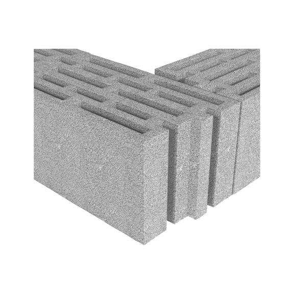
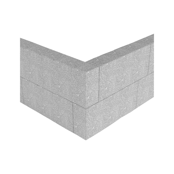
For fastening insulation panels in external thermal insulation composite systems (ETICS), e.g. expanded polystyrene (EPS), rock wool, cork and polyurethane, or lightweight panels made of wood wool
Select RAL-colour code
!! NOTE: On-screen visualisation of the colour differs from real colour shade!!